


Mail: info@anke-pcb.com
Whatapp/wechat:008618589033832
Skype: sannyduanbsp
What Is the Purpose of the Multiple Capacitors on a Chip’s Power Supply Pins?
As electronics engineers it is known that capacitors generally serve four primary functions: decoupling, coupling (blocking DC while allowing AC to pass), filtering, and energy storage. Today, I’ll focus on explaining the decoupling function.
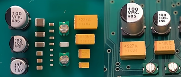
Common Types of Decoupling Capacitors
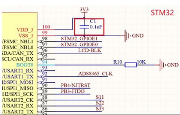
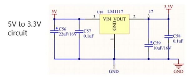
The image above shows a partial schematic of an STM32 series microcontroller’s minimal power supply configuration. This MCU requires five 3.3V power rails, which are typically supplied by an LDO (Low Dropout Regulator), such as the LM1117.
Why Decoupling Capacitors Are Necessary
While LDOs generally provide more stable voltages compared to DC-DC converters (e.g., the TPS5430), even LDO-supplied voltages can exhibit instability for high-performance chips. To address this, we place decoupling capacitors near the chip’s power supply pins. These capacitors absorb high-frequency AC noise from the power supply, diverting it to ground, thereby ensuring the chip receives a stable and reliable DC voltage. For optimal performance, decoupling capacitors must be placed as close as possible to the chip’s pins.
Why Is a 0.1μF Capacitor Commonly Used?
When studying power integrity, we often analyze capacitor like this way, at lower frequencies, the capacitor primarily functions as a filter. However, as the frequency increases, the inductive component of the capacitor becomes significant and eventually dominates. Beyond a specific frequency threshold, the capacitor’s filtering effectiveness diminishes. This means that at high frequencies, the capacitor no longer behaves as a "pure" capacitor. The actual filtering characteristics of a capacitor are illustrated in the curve below:
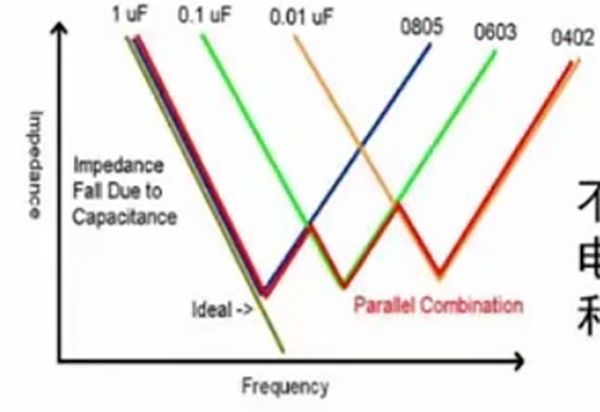
From the curve, the ideal filtering occurs at the lowest point of the impedance curve (minimum impedance). However, as frequency increases, a 0.1μF capacitor becomes less effective compared to a 0.01μF capacitor. At even higher frequencies, smaller capacitance values (e.g., 0.001μF) are required for optimal filtering.
Solution: Parallel Capacitors
To address this limitation, many circuit designs use multiple capacitors in parallel with different capacitance values. By combining capacitors of varying values, the effective filtering frequency range is expanded, ensuring better noise suppression across a broader spectrum. This approach allows for improved filtering performance over a wider range of frequencies.
Shenzhen ANKE PCB Co.,LTD
Post time: Mar-07-2025


